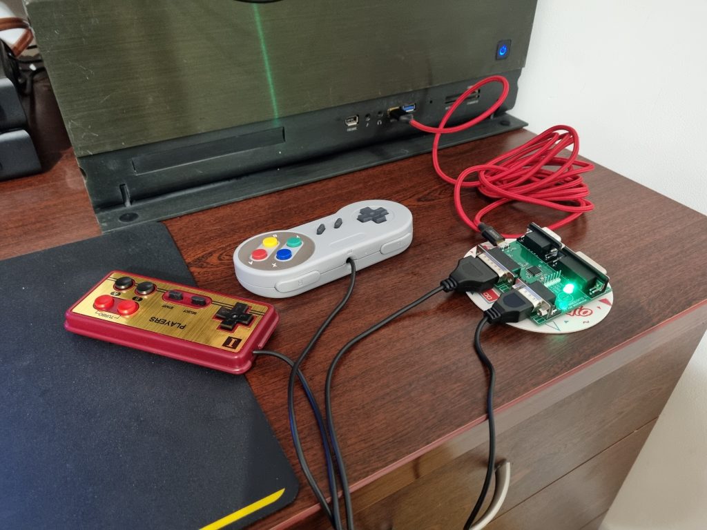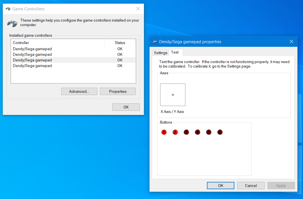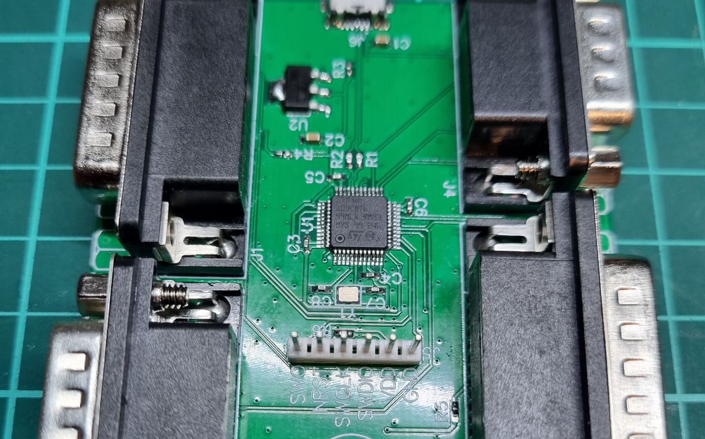
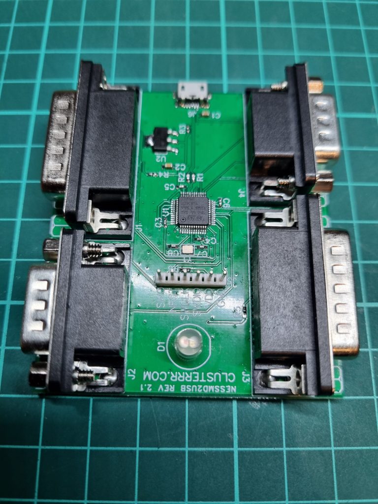
I built this NESMD2USB Famicom/Famiclone controller USB adapter by ClusterM, primarily for practice. This project is a great way to practice soldering and other technical skills. Soldering for this adapter requires advanced skills due to the 0402 size components, but with a microscope and a good soldering station, it becomes quite easy. The quality of your tools significantly impacts the ease of the project.
Looking at the design of the device. The component selection is dictated by the SMT32 processor. Thought I’m proponent of using the THT components for DIY projects when possible. If you can solder this processor to the PCB, then using through-hole resistors doesn’t make much sense. However, I question the choice of an SMD micro USB port. There’s plenty of space on the PCB, so why not use a through-hole USB-B port? A through-hole port would be more durable. Additionally, the PCB lacks mounting holes to affix it to an enclosure, which isn’t a major issue, but having them would simplify the enclosure design.
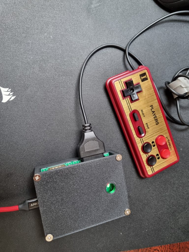
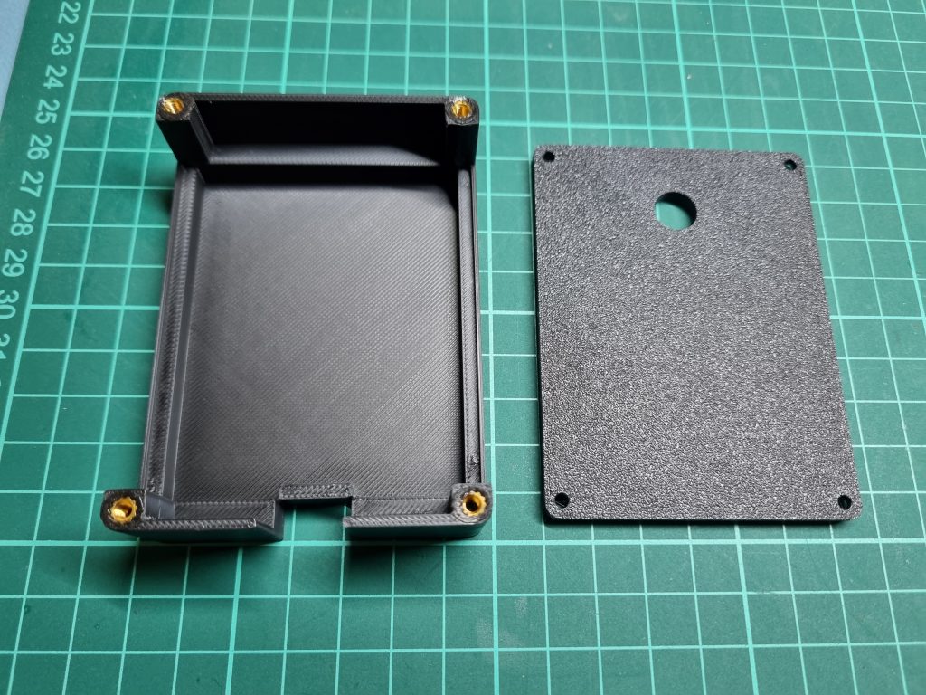
There were no 3D-printed enclosure designs available, so I quickly modeled one myself using Fusion 360. It uses heat inserts for M3 screws, but you can also glue it in place. I like that I can disassemble the device and reprogram it if needed. Here are the STL files for anyone who needs them.
The current firmware indicates it should work with both Sega and Famiclone (9-pin and 15-pin) gamepads. However, my original working Sega gamepad experiences errors in registering correct inputs, while Famiclone gamepads from AliExpress work perfectly. I suspect the author may have tested with knockoff Sega controllers. This issue could likely be fixed in the firmware, as the project is open-source. But for now, it suffices that it works well with Famiclone gamepads.