
Good for nothing? Some history and motivation
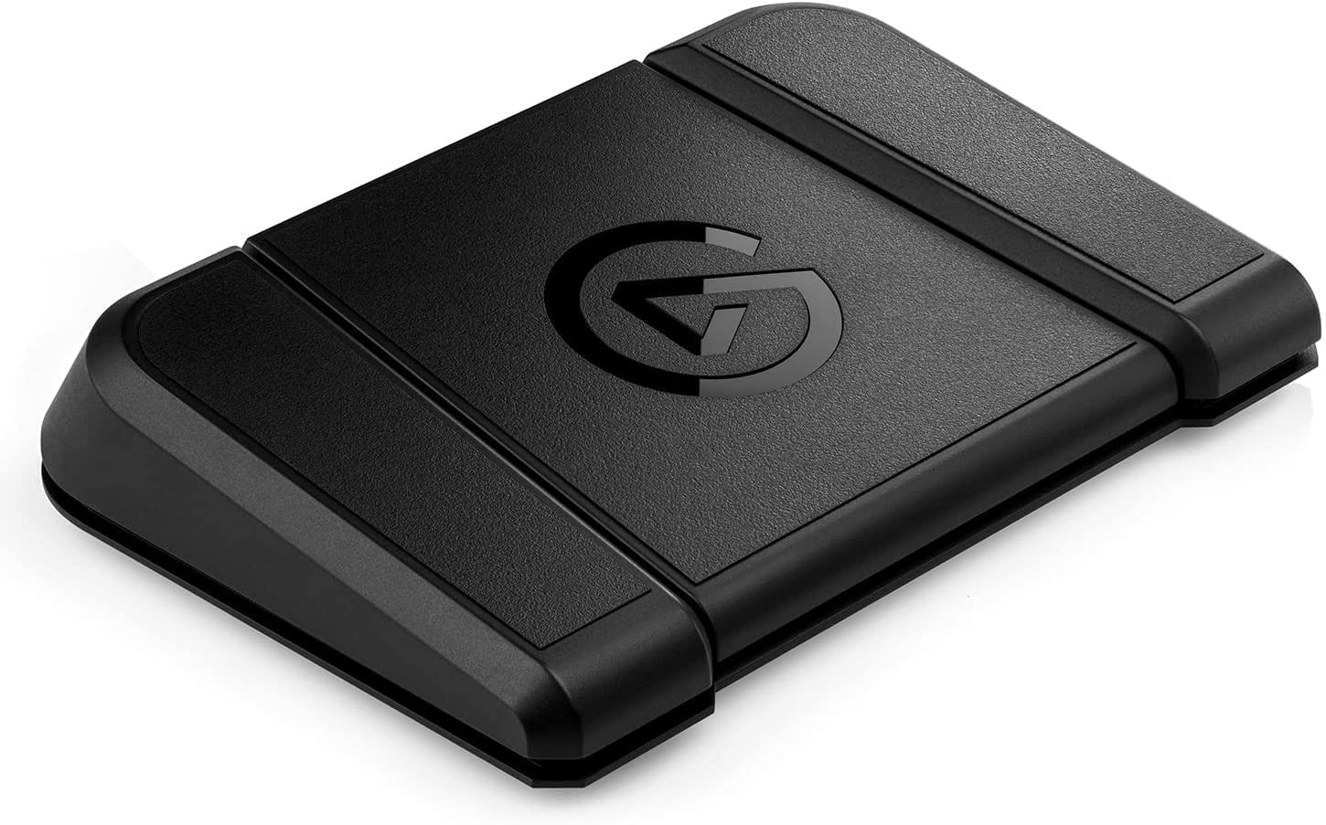
When Elgato Stream Deck Pedal was released it looked like a potentially great addition to Sinden Lightgun as arcade pedal. At a time I was considering using it on a PC with PS2/PSX emulation.
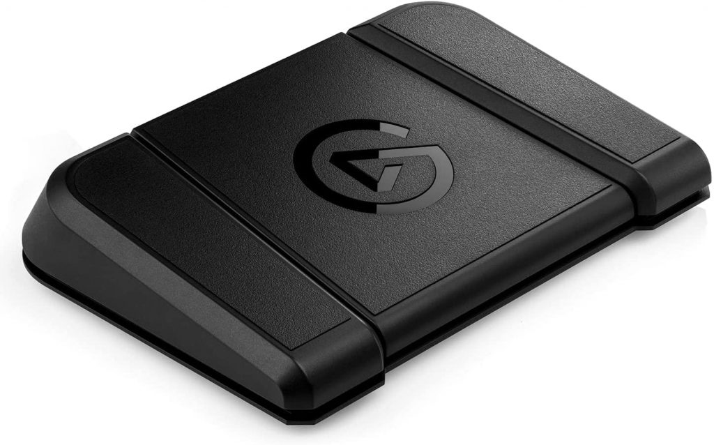
I bought me two of these for the hope I will be able to play Time Crisis coop with my friends. At a time I already had two Sinden Lightguns and arcade pedals seemed like a natural addition. Only later Andy Sinden had produced his own arcade pedals.

So I’ve managed to run Time Crisis on PSX emulator and setup Elgato pedal to work. However it proved to be quite difficult to emulate a single button press. It might sound ridiculous, but you actually need a third party plugin for this to work and even with that it’s not very reliable and not sure if it would work for two players on the same PC. So it was put into a drawer for later… I actually was trying to sell them at some point but unsuccessfully. No one seemed to be interested…
A year later I was getting into a new hobby which I would call retro computing. Yes, I was playing retro games before that, but this time I was getting more into the hardware side. I’ve rediscovered CRT’s and also learned that soldering and basic electronic skills are essential when dealing with old tech. And one time I thought hey I could hack those pedals and somehow install optical mouse PCB to emulate mouse clicks. Found a few yellowed Logitech mouses to dissect, but got intro other projects and this was postponed once more. But the idea now seemed promising.
At some point I got myself a Sega Saturn and later some Lightguns for it. These worked very well on my CRT TV. After restoring some Playstation 2 phat consoles it struck me that I could play Time Crisis on two CRT TVs and have a coop game using two consoles! Maybe I could hack Elgato pedals to connect to PS2 instead?
At a similar time Andy Sinden released his arcade pedal. But with all due respect to Andy paying 500 EUR for two pedals that are good only for a few games it seems to me overkill. I could find motivation for all kinds of silly purchases, but this one is beyond me. Sure it’s niche product and I wish Andy Sinden all the luck with great stuff he makes.
Hacking Elgato stream pedal
And by hacking I mean literally doing it with a pair of snippers. But on that later.
Lets open the device and see how it works. So the main board under the large pedal has most of the components and we are interested in those two chips I marked. These seems to be TMR switches which are ICs that detects presence of magnetic fields. You can find magnets in the cover of the pedal and they work by lowering them onto a switch. There are two switches because center pedal is wide and you probably could press it on the side and only one magnet will be low enough. Circuitry for the left and right pedals has the same components next to the switches as seen on the main board.
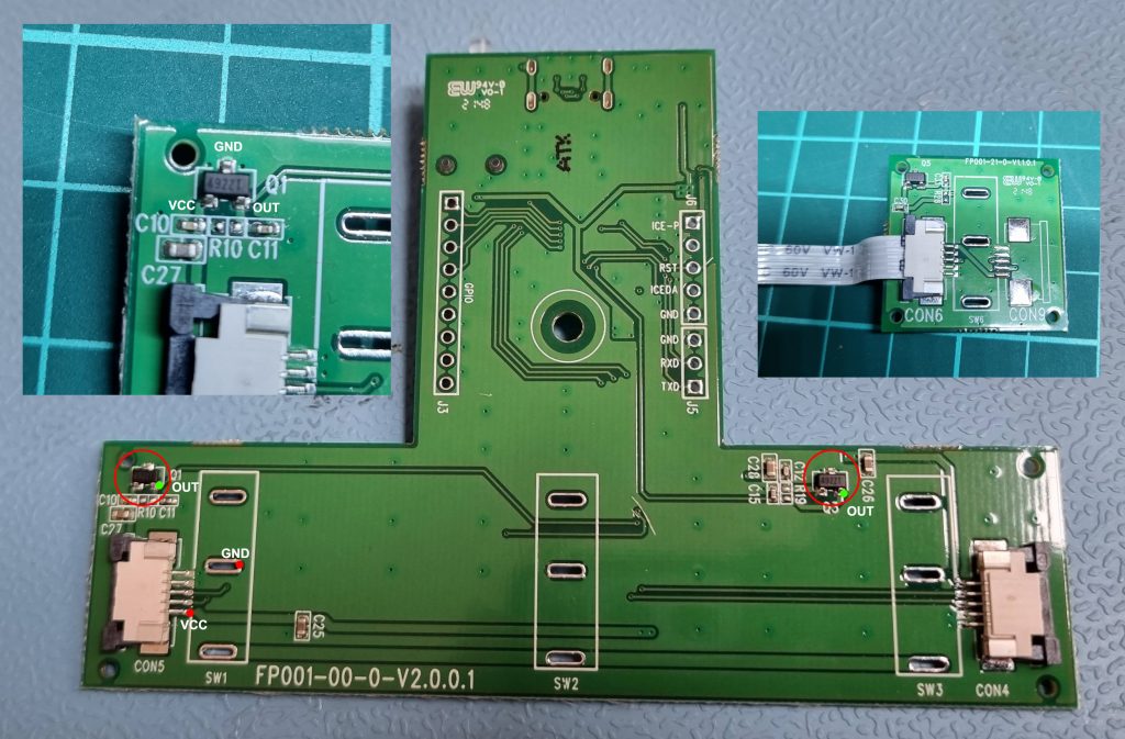
So what you need is to power those chips and redirect the output to PS2 controller. You could technically make all three pedals work, but for purposes of arcade pedal you only need one. It’s also convenient to store additional PCBs under left and right pedal covers, otherwise you will need some dangling box on the outside.
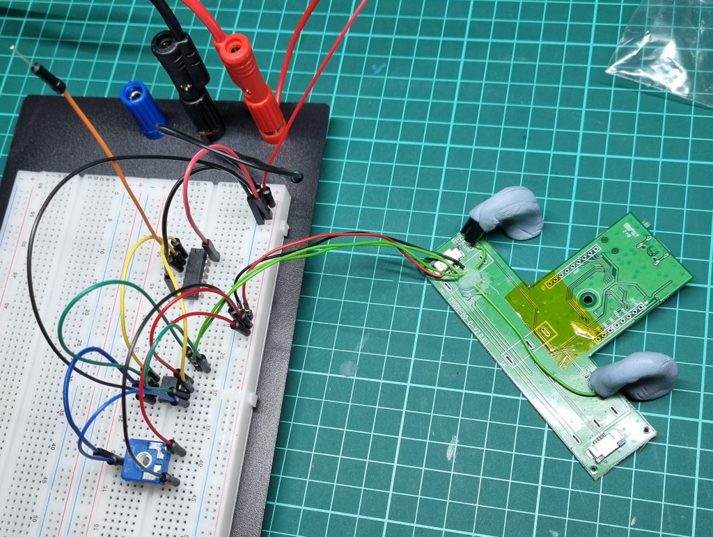
I would cut the traces to the controller chip, we basically don’t need all of the circuitry here. For the ground there are large pads available. For the power I would solder on the pin of the cable connector that powers left pedal PCB. And signal cables are soldered directly to the TMR IC output pins.
The switch output has following states:
OFF (or disengaged) – VCC / 2 V (half the input voltage on output)
ON (or engaged – the magnet is lowered) – 0V
To connect this to PS2 we will be using a PS2 controller. Here is a great resource for information on different PS1/PS2 controller PCBs https://slagcoin.com/joystick.html. There also plenty of other useful info relevant to building custom controllers.
For one of the pedals I have used the Playstation 2 Dual Shock A (Late Version) controller PCB. By shorting signal and common leads you get a button press. In picture it is L1 or R1 (it does not matter which button we are pressing).
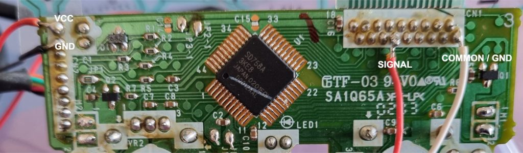
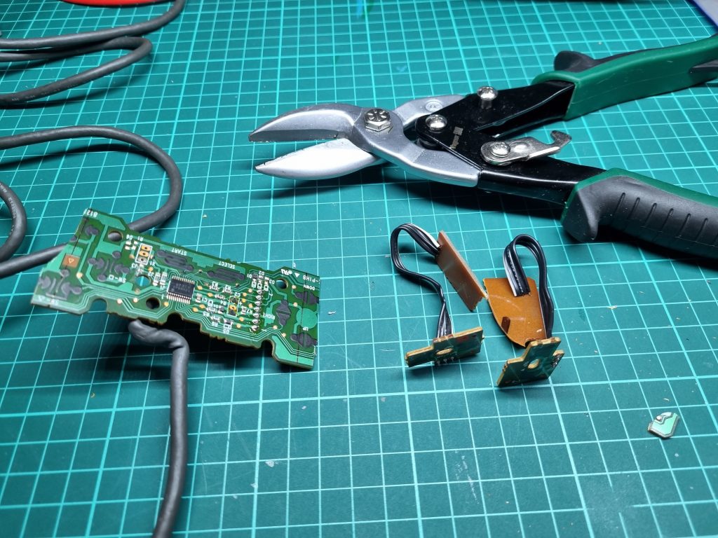
One problem with PS2 controllers is they have pretty large PCB and you can’t remove anything. So you are left with a dangling flexible PCB and it is good idea to wrap it with Kapton tape to protect from shortening or simply breaking. Also analog buttons take a lot of space. So I found that using Playstation 1 digital controller (one without analogs) is a way better option. What’s also nice about it is that you can trim it to take less space as shown here:
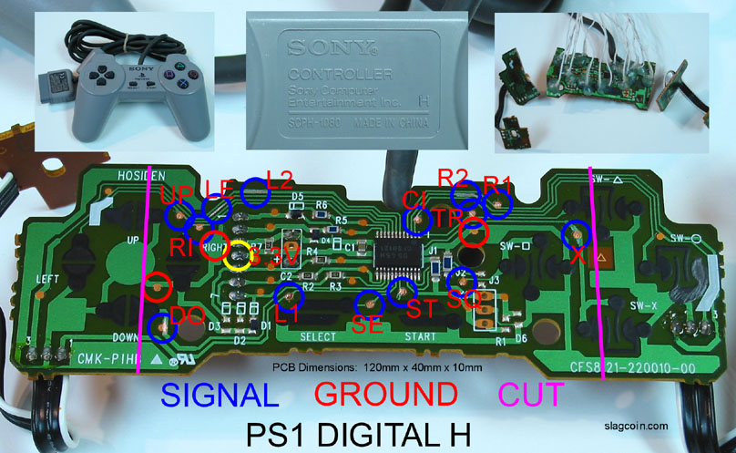
You can trim the PCB like shown in the picture, just don’t use tin snips it’s way too destructive…
Which button to choose does not matter too much for Time Crisis. But probably X would be sensible.
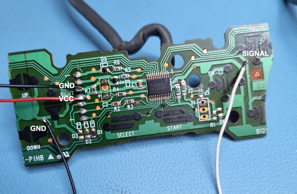
So now we have a controller PCB and all we need is to short signal and common when TMR switch is engaged. For that we will need a couple of additional components and a custom PCB.
Here is some primitive schematics I’ve done in Photoshop. These probably could be simplified, but you can get the idea how this works. Connections to the second switch are omitted for less clutter.
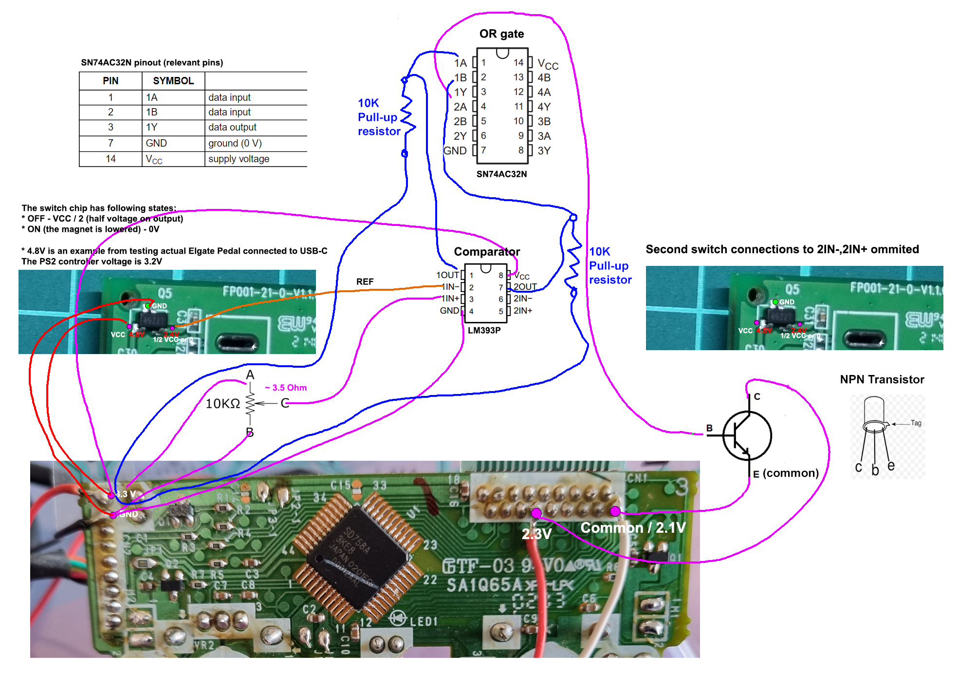
Components used:
- 1x 2N2369A NPN Transistor
- 2x 10K 0.25W Resistors (for use as pull-up resistors for comparator)
- 1x LM393-N Dual Open-drain comparator
- 1x SN74AC32N OR Gate
- 1x CA14-10K-H Adjustable 10K resistor / potentiometer. Probably regular 3.5K resistor would work too.
Let’s start from TMR switch, we have two of them, so we want that button press is generated when either of switches is engaged. Since the output of TMR switch is zero volts when switch is engaged we need some mechanism to make this into a signal. For that let’s use a comparator (LM393P) which compares two voltages and outputs logical 1 or 0 using following logic:
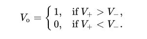
For V- (1IN-) input lets use output from TMR switch, for V+ (1IN+) input we need voltage that is lower than VCC/2 (disengaged state), so we need a resistor to lower the voltage. I used a potentiometer just for convenience, but it could be replaced by some 3.5K ohm resistor. Connect second TMR switch o 2IN- and same potentiometer output to 2IN+.
Now we need to make it work if either of switches are pressed. For that we will use an OR Gate (SN74AC32N) IC. You connect outputs of comparator to 1A and 1B inputs and 1Y output generates logical 1 of either of those are logical 1.
The output of OR Gate is then connected to NPN transistor base. The common (or ground) from controller is connected to emitter and signal to collector. When TMR switch is engaged the transistor “opens path” between emitter and collector thus shorting two leads and emulates pressing of a button.
More experienced builders don’t need much explanation here and probably would make this more elegant, but for learning amateurs like me it’s useful.
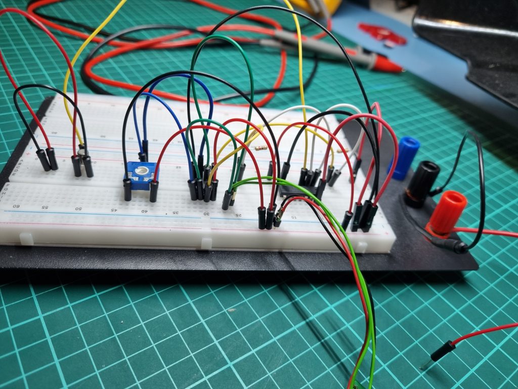
This is quite simple circuit, so it’s perfect for using a prototyping board (or stripboard).
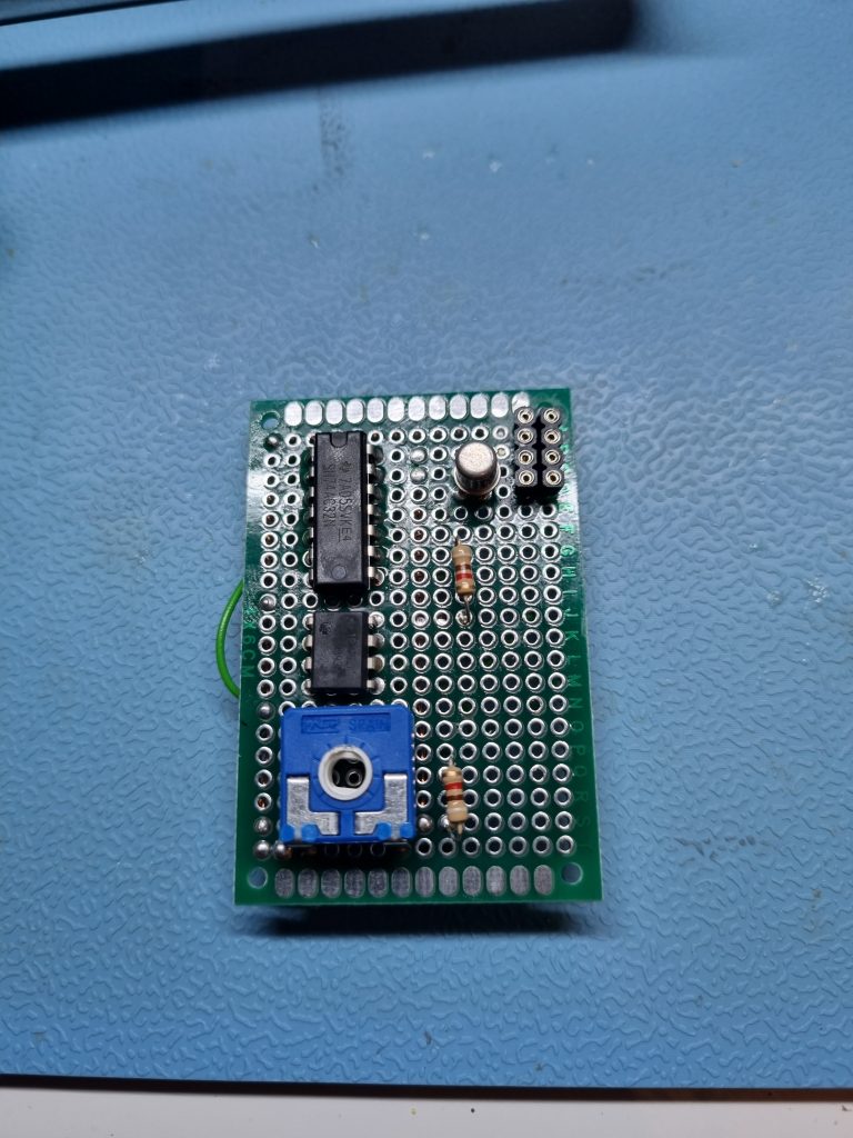
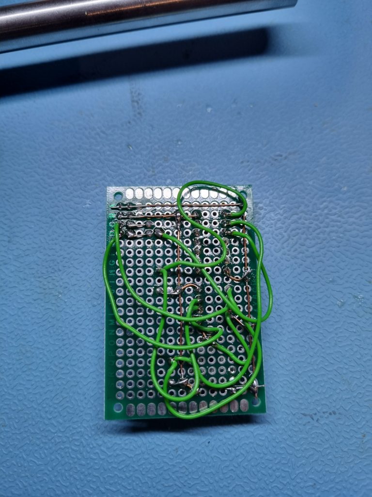
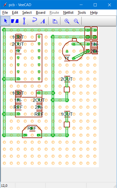
I recommend VeeCAD Stripboard Editor for designing prototype PCB. It’s very simple to use and you can print it for easier assembling.
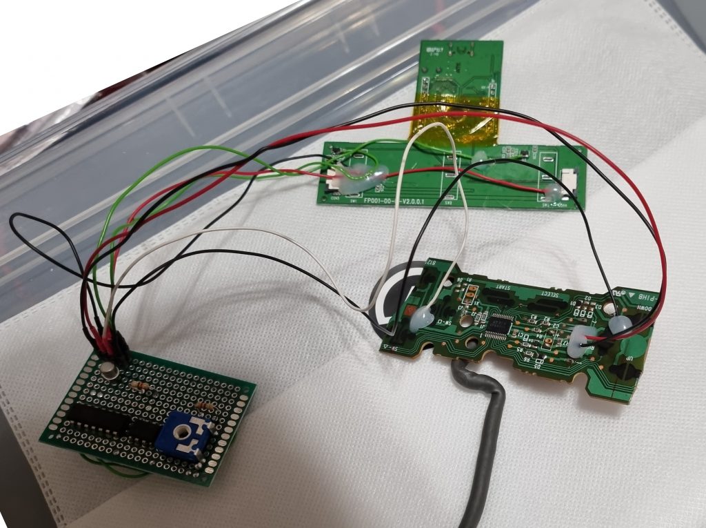
To connect all three PCB together I used a soldercup headers and interconnects so that I can disconnect them without desoldering if needed.
Now we need to place these PCB somewhere in the pedal enclosure. Since I need only single pedal I decided to use left and right pedal space for storing these PCBs. Here some cutting and hacking of plastic was needed. You won’t be using them as pedals after that anymore. As you can see PCB fits quite well.
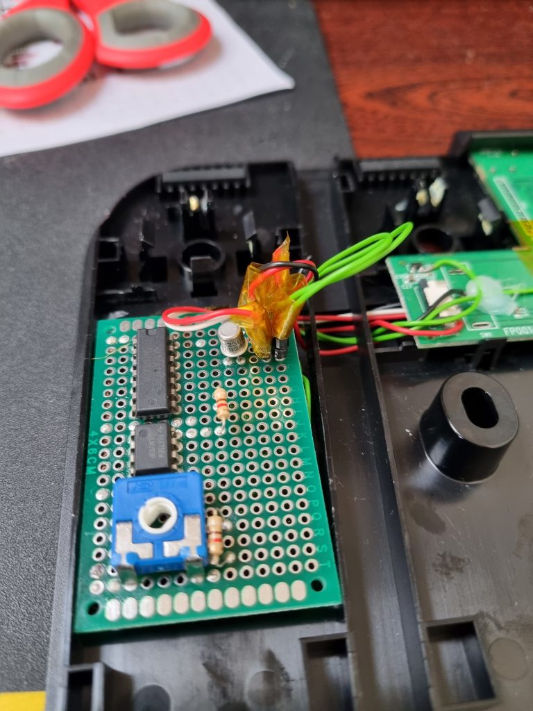
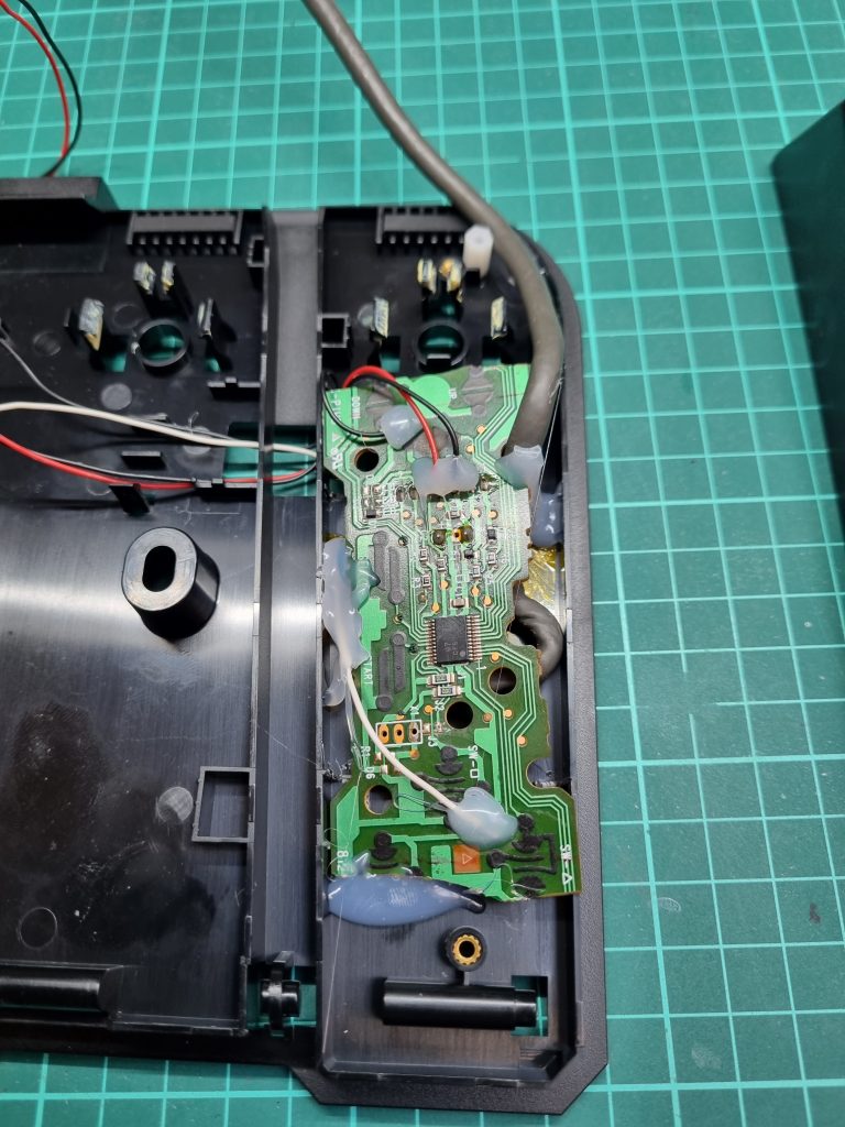
Some hot glue to fix everything in place and here is a finished product. I would recommend to add some glue into USB-C port too, so that no one would get an idea to connect this to PC or other device.
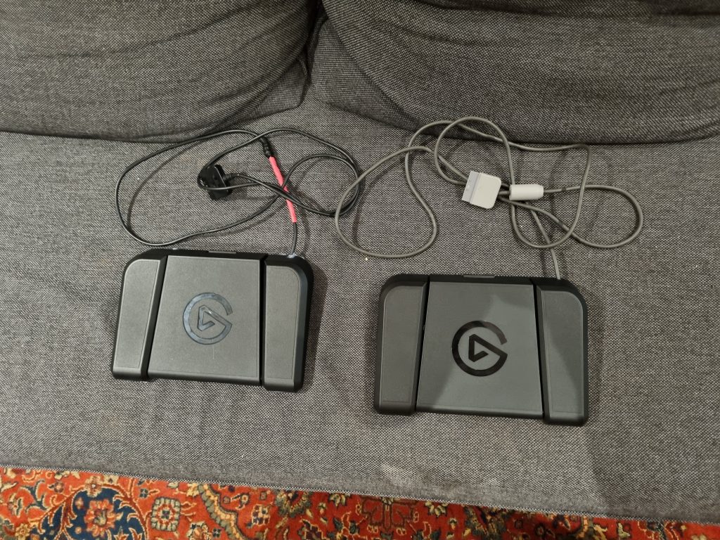
Now we just need to test it in a game of Time Crisis. But since I want to play coop game of Time Crisis I need to connect two consoles together.
Linking two PS2
Next we need to connect two PS2 consoles for a coop game of Time Crisis 2/3. The earlier phat PS2 consoles had a so called iLink port, which is essentially a 4 pin Fireware port. With a single cable you could connect two consoles, but it was also possible to connect even more if using Fireware hub.
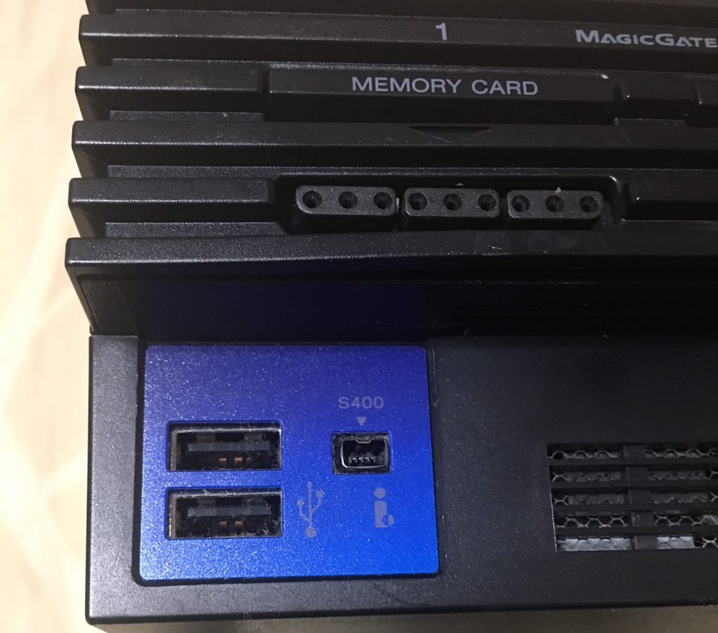
Since IEEE 1394 is already thing of the past it is not so simple to get a proper cable. You need a cable that has 4pins on both ends. So I bought some noname from Ebay for a couple of bucks and thought it will be fine, why it wouldn’t be?
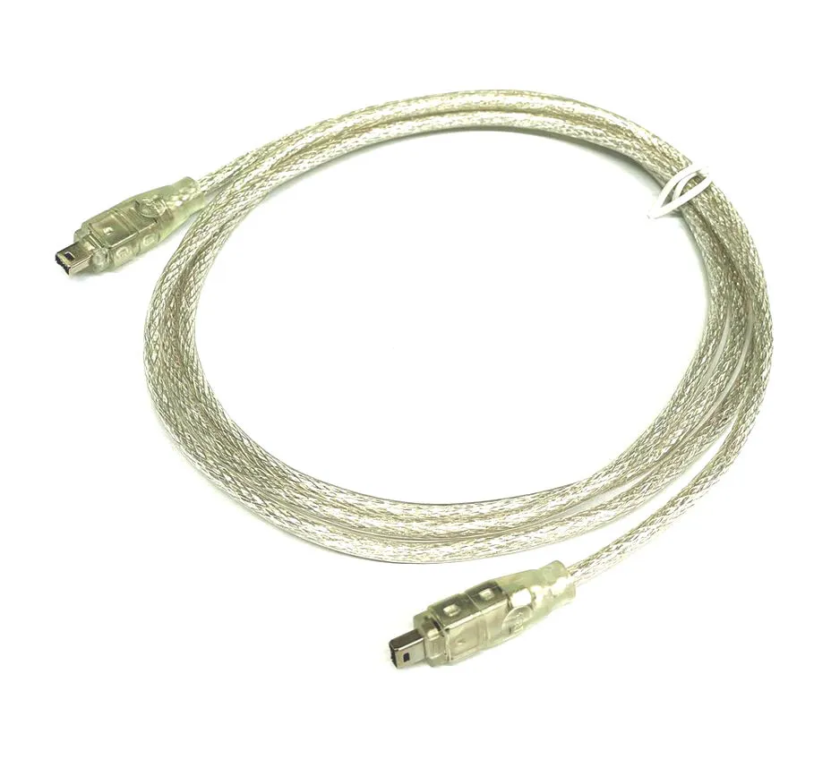
So I’ve installed latest Open PS2 Loader (OPL) on my hard drive and tried connecting two consoles. And it failed to connect. That was a disappointment. Nevertheless I continued searching for the evidence that it actually works and found couple of posts that said they where using grimdoomer’s OPL fork for that and that you need to enable Mode 2 option for game on both consoles. So I’ve updated OPL binaries and tried again. Still no success. Further searching on the issue I found couple of posts that said they replaced the Fireware cable and it started working. Mine seem to be intact and the seller advertised it like new old stock. But since I’ve had no idea what else to try, I’ve managed to find a better quality Fireware cable on our local Ad portal.
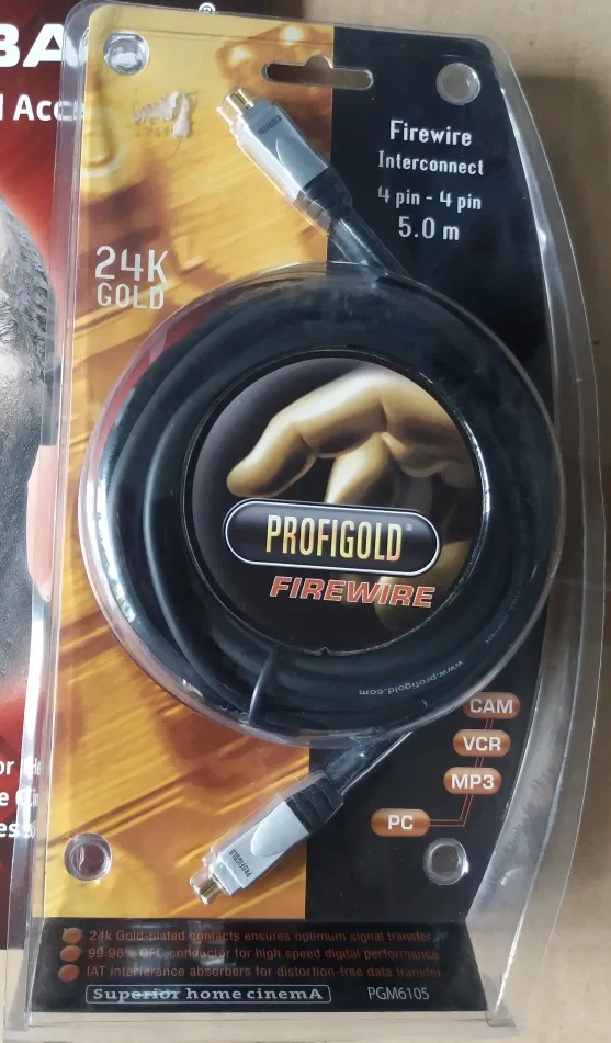
My hopes were quite low. I’ve attached new cable, started a Time Crisis 3 and initially was disappointed because even both consoles were interconnected the Link menu was still disabled on the first PS2. But when game loaded on another screen to my great surprise the Link option became enabled! The two player coop on two CRT TV’s was actually working now!