

When I started collecting CRTs my main concern was how will I get them fixed when the need arise. Nowadays rare technician (even with prior experience) will work on CRTs and it’s usually quite expensive. In my experience no one wants to do a full recap, due to amount of effort needed.
Getting more and more into retro computing hobby I realized that you have to learn to fix equipment yourself. So I got myself Hakko FX-888D and started soldering. My first project was a GBS-Control device. From almost zero experience in two years I was already working on most complex mods and had pro equipment at home.
One of the major milestones was achieved when I repaired a CRT monitor. Which at that point was not at all complicated, but you still needed to defeat any fears of working with high voltage equipment and most importantly know what you are doing. It takes time to get yourself comfortable with fixing a CRT.
Broken Philips from a basement
At the time of acquiring this monitor I already had bunch of Commodore 1084 monitors that I bought on German Ebay. I like these little guys, even though I don’t use them very often, since I got 14″ Sony PVM. Commodore monitors were not very common in Lithuania and I was surprised to find one in our local ADs site. So I went to some basement of apartment building and brought my self a Philips CM 8833 MK II in an unknown condition. The monitor looked a bit battered, but the screen itself was in perfect shape. The RGB D-SUB port was wobbly, my first thought was that someone kicked the back on the monitor and broke the PCB. Another common problem is broken power button that does not stay in place. Because of these issues I did not wanted to power it on before the repair. Broken transformer unit is quite common for these monitors and you can’t know if you would be fixing monitor that is pretty much dead.

A tip: careful with cleaning the tube, because it’s not all dirt, it’s graphite that makes that tissue black.
Funny thing is that I was recording all the disassembly process with a camera mounted to my head, but later found that it was pointing to high and I did not see actual cables and stuff that I disconnected. At least I made some photos.
Dim-bulb tester
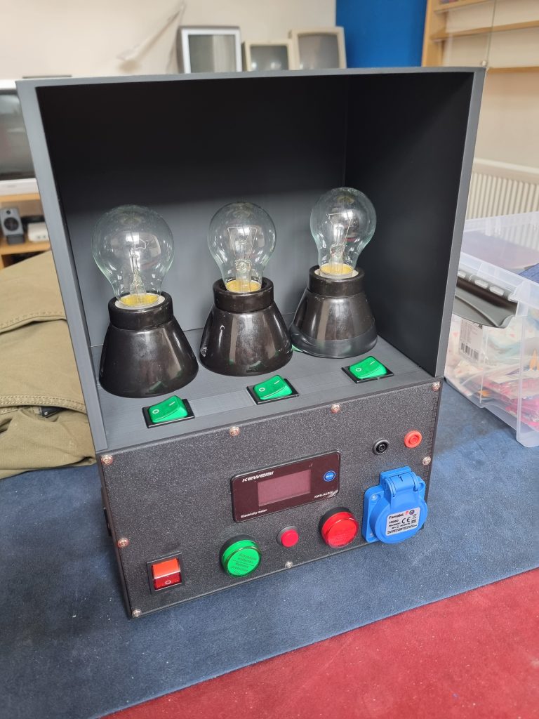
Watching Youtube videos I find out that there is a device used for testing vintage electronics for short circuits. It uses now obsolete filament lamps. The point of this device goes around the idea that filament lamp connected in series with the device under test (DUT) works as a current limiter that will “absorb” excessive current in case of short circuit or other fault. You can check the video demonstration below where I make a short.
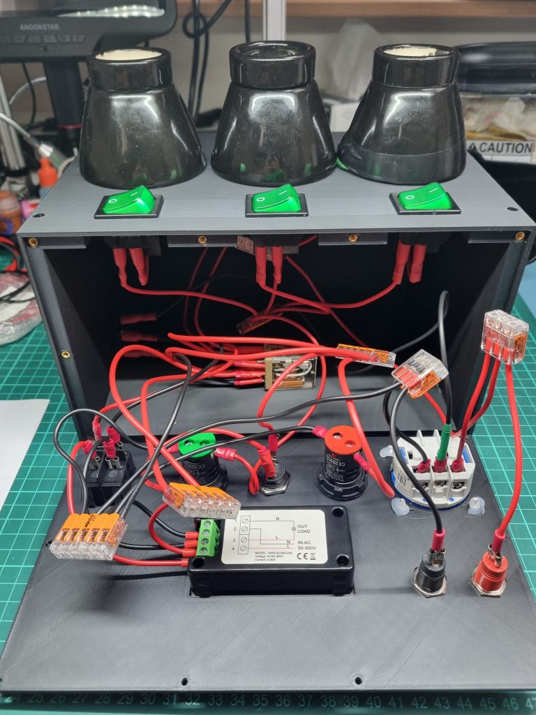
You can’t buy this device, you have to build it yourself. Sure, you can make a very basic version of it, but why settle for less when you can make a premium version. So I started designing my own, yes designing, because I wanted to understand how everything works and there wasn’t really any complete plans available to build one. My device uses relay for switching between current limiter and direct power. Initially it starts in current limiter mode (green) and you can press momentary red switch to change it to full power direct mode (red). I also modelled and printed a plastic case for it (the top cover is only for storage and should be removed when lamps are on. Assembling this I was thinking that I have never fixed even electric outlet before and now I’m building a device that operates on dangerous 220V.
The Repair
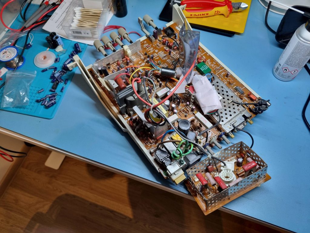
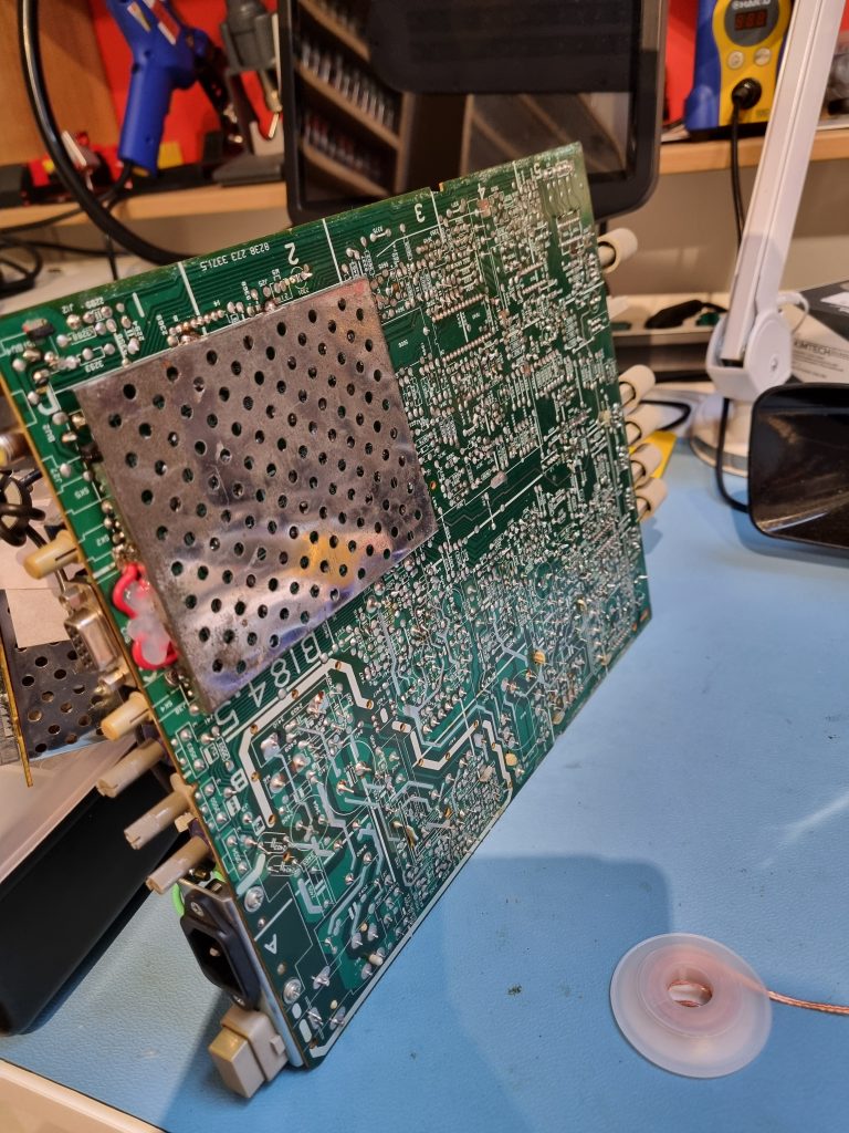
So after disassembling the monitor I actually found less damage than I had imagined. The video port was loose and some traces were broken, but not whole PCB as I was afraid. I reconnected broken traces with wires and fixed them with hot glue. Had to glue the port with green stuff in place. Replaced all the capacitors with new ones. I’m not a big fan of premature capacitor replacement for working devices, but in this case the device is really old and capacitors do degrade, so it seemed only natural. Now the power switch was a bit more trickier. The replacement is not a direct replacement and modifications were needed for mounting to work. New switch did not have the same metal parts to mount it in place. So I’ve tried removing them from old switch (that was easy, because I cut off plastic with pliers) and adding to a new one. In the process I broke the new switch. Good thing I have 5 of those. So I decided that instead of mounting it I would just glue the switch in place (with green stuff again). Sure it is impossible to remove it now, but I don’t think I will need it replaced again. So after cleaning all the dust and reassembling I was ready for the testing.
Testing
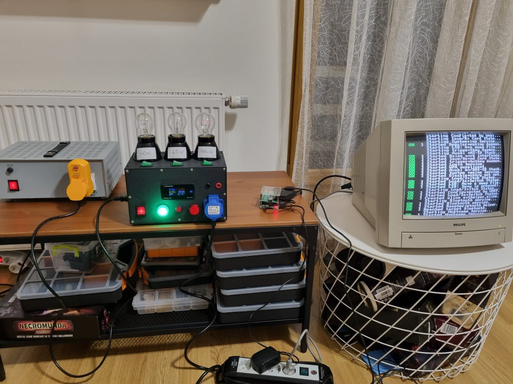
For testing I employed Isolation transformer, ground leakage tester (the yellow device) and my own Dim-bulb tester. As a video signal source I used Raspberry Pi with RGB SCART hat.
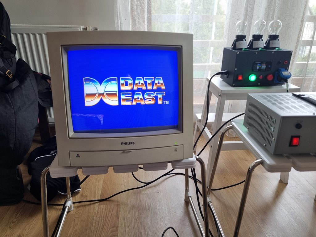
Oh was I happy to hear and feel the static on the screen and see phosphor glow again. I would say that the screen is in a perfect shape. Bright and vivid.
Conclusion
This project now makes me confident that now I can fix any CRT. Well, probably not, but at least I no longer need a help of a TV technician. Something that was more of a dream few years back was actually happening.
But thinking of it building a dim-bulb tester was more demanding work and equally important achievement.